Tiny OLED Board
I’ve been working on a software library named Tiny4kOLED for the ATTiny85 chip to control a 128x32 pixel OLED using the SSD1306 chip. (The 4k in the name is because that is how many pixels there are in total.)
The software for the library is available on GitHub.
On the hardware side, I designed a small prototype board that I thought I’d share.
Parts:
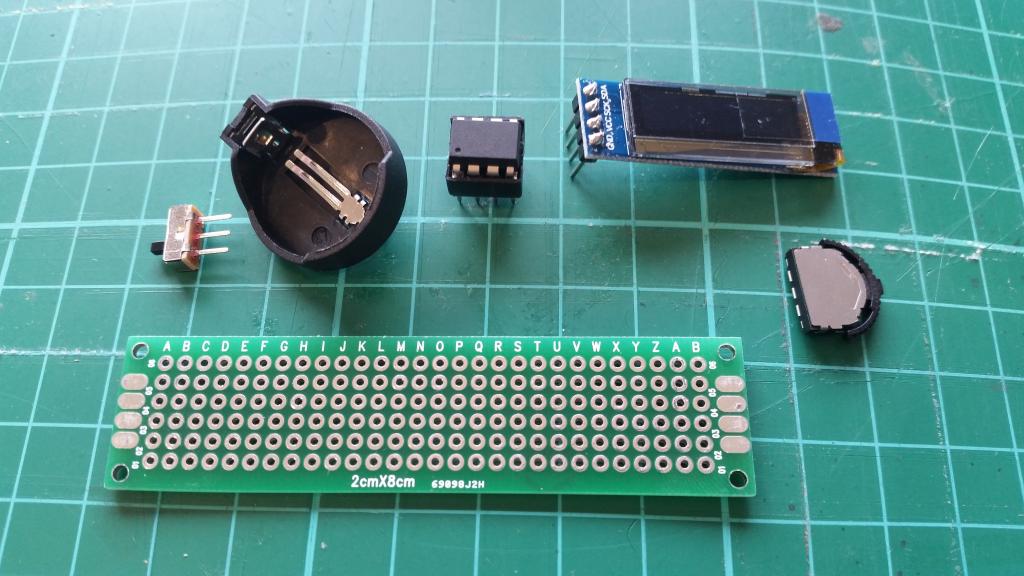
- One prototyping board, 2cm x 8cm in size, with 28x6 hole with 0.1” spacing. US$1.79 for 10
- One small switch, SS12D00G3 US$0.49 for 10
- One CR2032/CR2025 coin cell battery holder, US$0.89 for 10
- One CR2032 coin cell battery, US$1.99 for 10
- One 8-pin DIP socket, US$0.47 for 10
- One 8-pin DIP ATTiny85V-10PU, US$13.77 for 3
- One 128x32 SSD1306 OLED, US$14.85 for 5
- One thumbwheel toggle switch, US$1.87 for 10
- Wire, Solder, etc.
That’s about US$8.31 each, if you buying enough to make ten, 90% of which is the chip and the screen.
The DIP8 ATTiny85V-10PU is hard to find, and four time the price of the ATTiny85-20PU, which you can get at US$11.50 for 10, but they’re able to operate at a much lower voltage, so can make much better use of the battery.
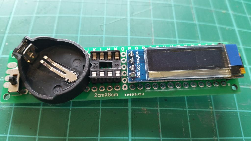
Here’s my design. The wires are mostly on the bottom of the prototyping board. It is only the curved parts of the wires that are on the top of the board (under the OLED). The thumbwheel is not on its own board:
The thumbwheel toggle switch is designed for surface mounting, but luckily, it has a couple of small plastic lugs on the back that snap into the holes in the board, and the electrical connections are positioned close enough to holes to allow you to solder the switch to the board.
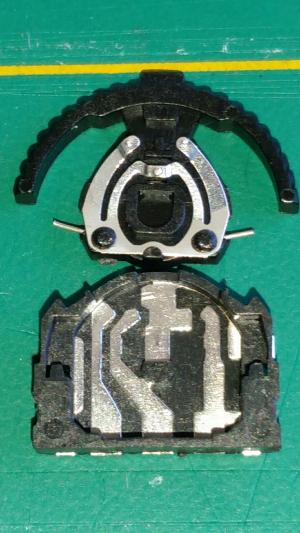
I took one apart to see how it worked. The three little blips on the moving part result in connecting the three base contacts to the top, which is the piece of metal ending in the connection on the right:
I position this on the right hand side of the board, operating as an up/down and selection switch. It fits nicely under the OLED, which helps to stop it breaking loose with use. The first time I used one, I tried soldering wires through the holes, and tried to get the solder to bridge over to the pads. That was difficult, as the solder wanted to stick to the wires. This time, I discovered that it is possible to solder it on by flowing solder down the relevant holes from the back, and checking the connection from the front. My plan was to form solder bridges along the breadboard, but after making a mess of that, I solder-tacked wires onto the board.
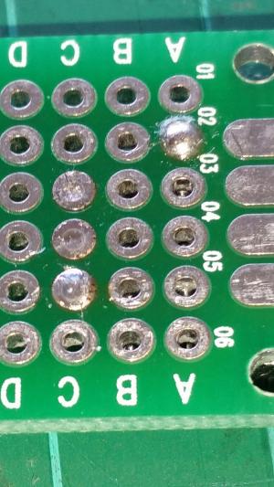
Here’s the positioning of the thumbwheel (I have no idea why the reverse of the board doesn’t use the same A-Z,A,B for the holes as the front! The upside down D, C, B, A in the image are actually Y, Z, A, B on the front of the board):
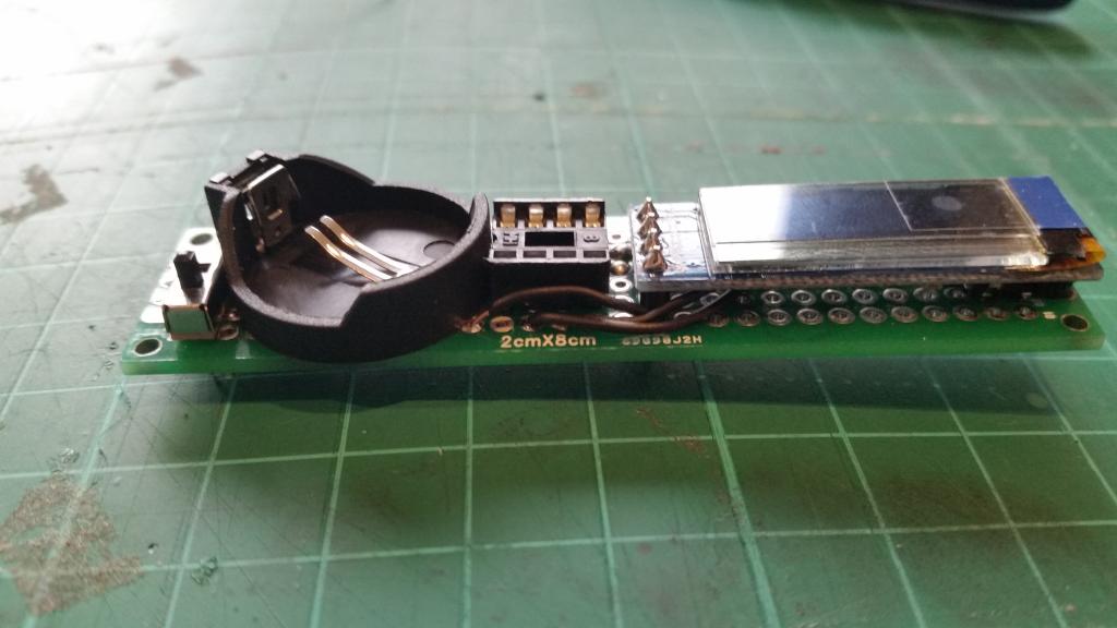
I then soldered in the switch, battery holder, 8 pin socket, and the OLED:
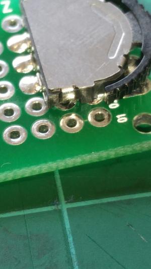
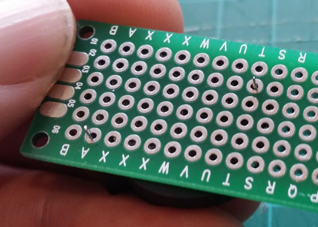
Here’s where the battery holder pins come through. The connection in the base of the holder can come loose, so make sure it is pushed through properly when you solder it (and don’t get distracted wondering why the alphabet on the back got stuck at X):
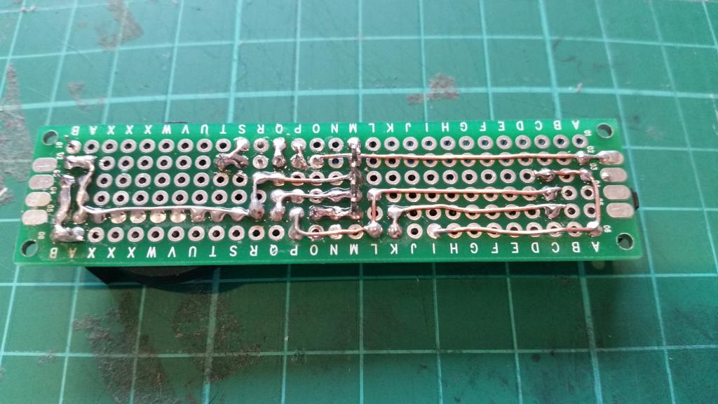
Then I solder-tacked wires according to my design. I started from the left, and quickly changed how I was doing it. I also re-designed how I was going to connect the insulated wires. The same kind of copper-core wire is used throughout, mostly entirely stripped of insulation. For the two wires that loop under the OLED, the wires are continuous and have had only half of their insulation stripped off. (The wire ending on a pad does not have any reason to go to the pad.):
I use two DIP8 sockets, so that I can keep the ATTiny in a socket, with that socket plugged into the soldered socket. I remove the socket with the ATTiny in it when I want to program it, as its much easier to remove than trying to remove the ATTiny from the socket.