What's wrong with my High-voltage Serial Programmer?
There’s a common High-voltage Serial Programmer circuit online for resetting fuses on the ATtiny85 (and similar). They use a 12V power supply, which I don’t have. I decided to experiment using a cheap DC/DC converter.
What for?
The ATtiny85 chip only has 8 pins, two of which are used for power and ground.
One of those pins can used to reset the ATtiny85, or by changing ‘fuses’, can be another general purpose Input/Output pin. However if that pin function is changed, the ATtiny85 can no longer be re-programmed.
Other fuses control the clock source, and when experimenting with some of my ATtiny85 chips, I had inadvertantly set them up to require clocks that meant my programmer could no longer communicate with the chips.
A ‘High-voltage Serial Programmer’ (HVP or HVSP) allows these otherwise bricked chips to have their fuses reset, allowing them to then be re-programmed.
They’re called ‘High Voltage’ because a 12V signal needs to be supplied to the Reset pin to put it in High-voltage Serial Programming mode.
DC/DC Converter
The converter I had was a B0512S-1W, which created a 12V power supply from a 5V input. This is probably a bad option, as we’re only using the 12V as a signal, and not drawing much power from it. One of the datasheets I found for it says …
this product should never be operated under no load! If the actual output power is very small, please connect a resistor with proper resistance at the output end in parallel to increase the load, or use our company’s products with a lower rated output power (B_S(D) -0.25W Series).
However, it was cheaper than any 12V power supplies I could find, so I thought I would give it a go.
I’m left wondering though - is there a better option than the B0512S? Should I introduce artificial load? What happens with next to no load?
Breadboarding
I tried it out on a bread board, with an Arduino UNO as the controller. I used the same pins as I’d seen in the circuit diagrams online, using the UNO board’s pins 8 to 13.
It worked!
Design
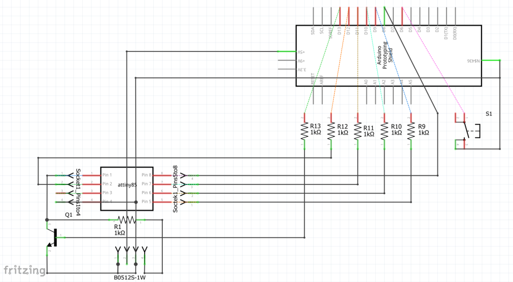
So, I designed a layout for a prototype board, shaped to sit on top of an Arduino UNO.
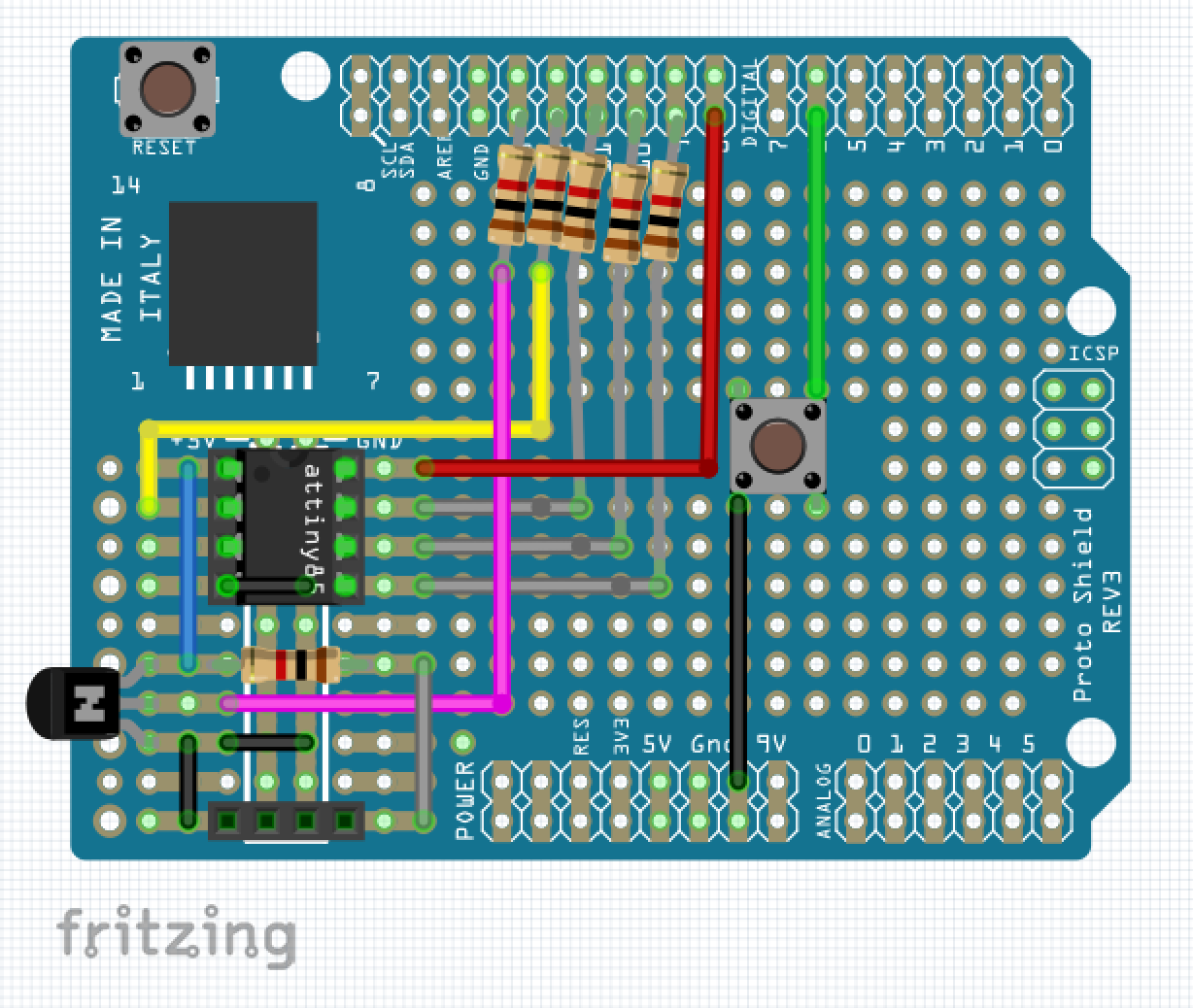
(The 4 pin socket at the bottom is the B0512S-1W.)
Build
I was thinking that the resistor legs would be long enough to go from Arduino UNO pin 9 to ATtiny socket pin 5, however I forgot that when I soldered them at the top by the pins and consequently had to use some additional wires and joins. I rearranged the Fritzing design afterwards to look more like what I had built.
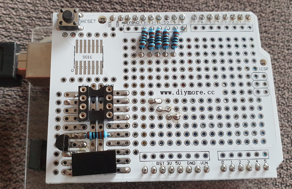
I added the button after taking these photos. The purpose of the button is to allow resetting fuses without having to control the UNO from my laptop.
Test
It didn’t work!
I had had it working on a breadboard though!
Debug
I spent the rest of the afternoon trying to figure out how come the device signature wasn’t reading correctly:
Is the Attiny85 completely bricked?
- No, I get the same behaviour with known good devices that can still be identified as ATtiny85 devices and re-programmed after having been in my High-voltage Serial Programmer.
- I did read all the code a good number of times, and examined the relevant datasheet, learning a lot about high-voltage serial programming, but not discovering any reason why mine might not be working.
- The signature was being read as FFFF. I changed the code to ignore the signature, but then the fuse values were being read as FF, and any attempt to write different values had no effect on the ATtiny85.
Is sharing pin 13 with the built-in LED on the UNO a problem?
- I don’t think so - but if you’re building your own I recommend using a different pin to control the 12V signal. The built-in LED on my UNO is underneath the prototype board, but its light shines through the holes in the prototype board. The sketch I was using was turning the LED on and off, but even with that code commented out, the problem remained.
Is the transistor wired in the correct way around?
- Yes. I think so. It’s a 2N2222A, not a P2N2222A.
Are any of my solder joints bad?
- They’re not pretty, but they all beep out ok.
Why, when the 12V signal is switched on, does the ATtiny85’s Reset pin only get about 7.5V?
- This is definitely a problem. The B0512S-1W is putting out a steady voltage of about 12.5V, which is at the high end of what the ATtiny85 will accept for a 12V signal.
Is the transistor broken, and I’m getting a voltage divider circuit between the 12V supply and the 5V on pin 13?
- I tried testing the voltage drops across the transistor pins, though with the transistor in circuit rather than removed. I’ve never done this before, and I think that the diode testing portion of my multi-meter can do this. There was one unusual reading - the emitter to collector voltage drop was 2V rather than OL. I don’t know if this indicates that there is anything wrong with the transistor.
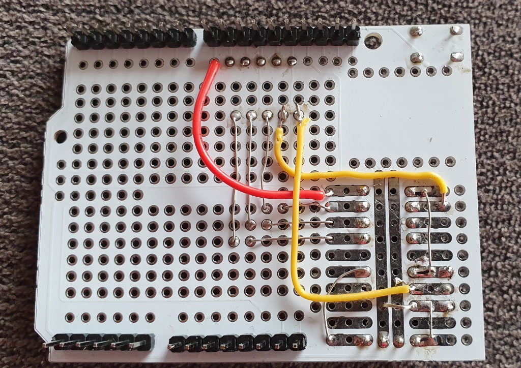
Eventually I found the cause, and if you know what you are looking for, you can see it in the image above – I had completely missed wiring the ATtiny’s ground connection! With that fixed…
It works!.